Written by Tony Stanton, Engineering Manager, Gurit
Few cars have achieved the visual impact or enduring appeal of the Jaguar E-Type, the iconic British sports car launched in 1961. With its long bonnet, sweeping curves and distinctive proportions, the E-Type became a benchmark for automotive design.
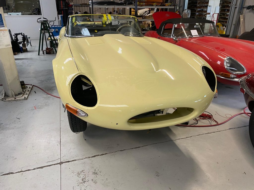
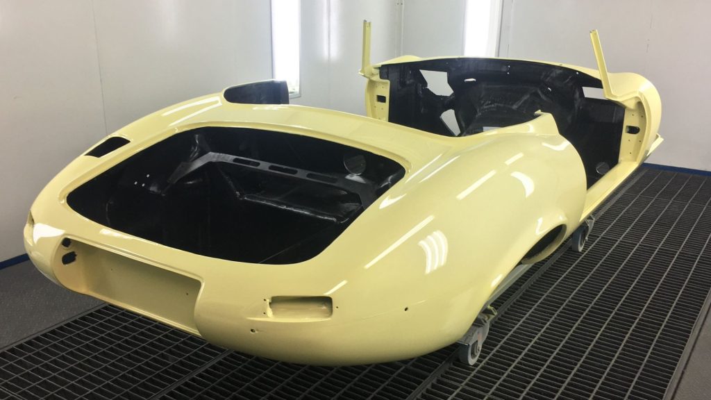
More than six decades later, Beacham has reimagined that classic shape in the CFE (Carbon Fibre E-Type), retaining the character and proportions of the original while delivering the performance, reliability and functionality of a modern Jaguar. Behind the familiar silhouette is now a fundamentally different structure. Gurit was commissioned to develop the carbon-fibre laminate specification and assess its structural performance, using detailed finite element analysis to engineer a lightweight chassis for the demands of a modern drivetrain.
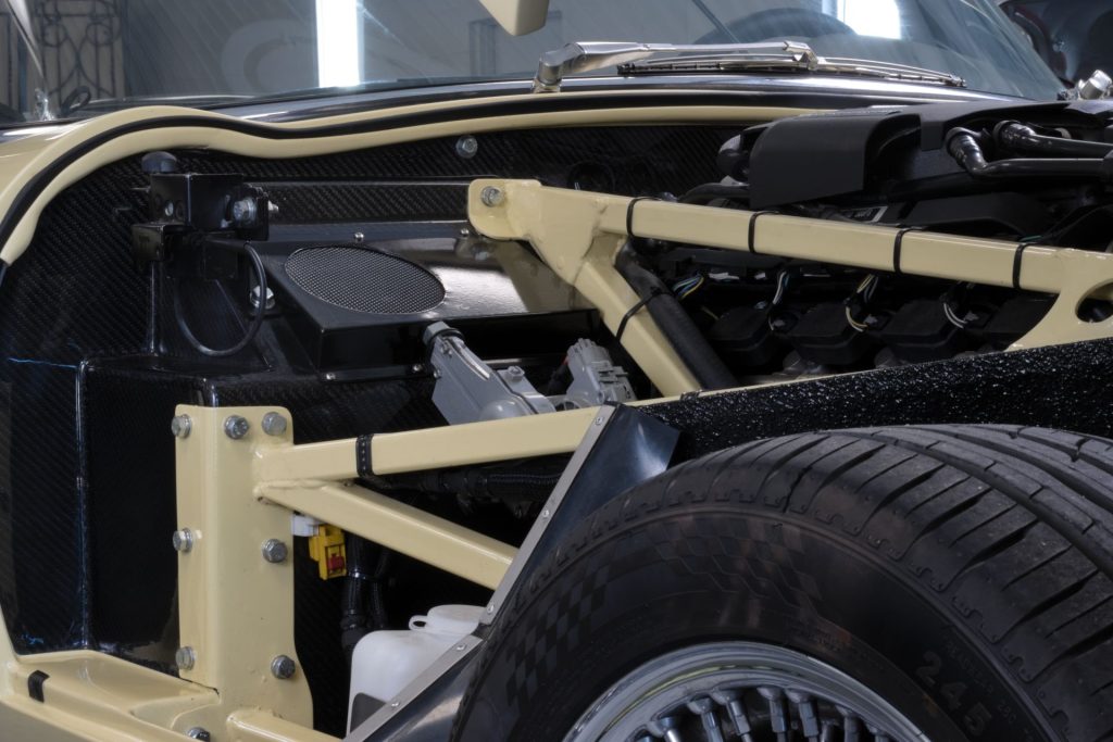
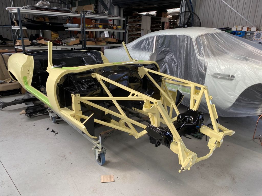
Achieving that required an entirely new carbon-fibre structure, substantially lighter than the original steel construction and engineered for the structural loads of the CFE, including frontal impact. Composite materials behave differently from steel, with strength and stiffness determined by fibre direction, laminate construction and the way loads are introduced into the structure. While the overall chassis geometry and adjoining metal assemblies were designed by others, Gurit’s analysis incorporated the wider chassis system, tracing loads from the suspension and forward metal spaceframe into the carbon tub. The forward metal frame forms a key part of the energy absorption structure in a head-on impact.
Starting with the loads
Gurit established a defined engineering methodology for the structural assessment, based on limit-state principles. Serviceability conditions, including deflection, clearances and normal operation, were assessed separately from ultimate load cases addressing strength, rupture and buckling. Nine load cases covered static and road-going conditions, including the vehicle’s static weight, a vertical jounce representing a severe road input, hard front and rear braking, single-wheel kerb impacts, diagonal chassis twist and torsional stiffness. The braking cases applied a horizontal load equivalent to twice the associated vertical wheel load. The kerb-impact cases applied a lateral load 2.5 times the vertical component at one wheel, while the twist cases applied three times that component at one chassis corner.
The target was 50 percent greater torsional stiffness than the measured steel reference structure, exceeding the low-volume vehicle guidance used for the programme. Five simplified impact cases included two 260 kN frontal load cases, applied through different parts of the forward frame, and 66 kN cases at the door attachments, sill and rear wheel-arch structure.
These were simplified, quasi-static load cases for assessing load paths and identifying vulnerable structural details. They were not physical crash tests, time-dependent collision simulations or whole-vehicle crash certification.
Modelled one ply at a time
The composite structure was modelled with shell elements to account for carbon fibre’s orthotropic properties. Each ply was modelled individually, allowing the contribution of 0/90-degree material, ±45-degree reinforcement and unidirectional carbon to be assessed. The forward spaceframe, wishbones, uprights and other metal components were represented with beam elements, while spherical suspension joints modelled load transfer. Fourteen individual point masses represented major items including the engine, gearbox, doors and occupants.
Under the 3g vertical jounce case, the model predicted 5.5 mm of deflection at the middle of the sill and a 4.0 mm reduction at the top of the door aperture. The results provided data for assessing door operation and panel clearances.
Where the analysis earned its keep
The impact cases identified local load concentrations at the interface between the metal spaceframe and carbon firewall. The analysis recommended changes to the load path, including extending and wrapping metal end plates to distribute forces, increasing a critical mould radius, adding tapered solid-carbon reinforcement and tying a forward infill panel into the firewall to remove a vulnerable free edge. Local laminate reinforcement was specified around the firewall mounts, suspension locations, gearbox attachments, door hinges and locks, sill ends and rear-impact areas.
Continuous high-modulus unidirectional reinforcement ran through the sills to increase chassis torsional rigidity. Away from load introductions, thin-walled honeycomb structures provided stiffness with lower mass, while additional carbon was concentrated around fittings and other highly loaded areas.
Stiffness without the mass
The proposed composite chassis was estimated to weigh approximately 100 kg, including ply overlaps at corners and edges, compared with 260 kg for the steel reference tub. The carbon structure therefore achieved the required performance at approximately 38 percent of the steel tub’s mass.
With high-modulus reinforcement in the sills, the modelled carbon tub delivered 77 percent greater torsional stiffness across the floorpan than the steel reference—approximately 1.8 times the stiffness at considerably lower mass. On a stiffness-to-weight basis, the carbon structure was around 4.5 times more efficient in torsion. Across the complete wheelbase, including the forward and rear metal assemblies, the predicted improvement was 39 percent. Once the carbon tub became sufficiently stiff, a significant proportion of the remaining chassis twist occurred in the forward metal spaceframe.
The results also showed the importance of assessing the complete structural system. Increasing the stiffness of one component can shift the limiting behaviour elsewhere in the chassis. The preliminary report recommended testing as-built laminates to confirm that manufactured properties matched the design assumptions, with further fatigue and through-thickness assessment.